Dynamic Clutch & Brake Selection for Dry Running Applications
by Michael E. Gamache, President, Carlyle Johnson Machine Co.
Utilizing Clutches and Brakes
The selection of clutches and brakes is affected by several factors relating to a specific application. This paper will discuss how to evaluate the operating requirements and determine the appropriate clutch or brake. In addition, the best type of clutch or brake actuation and how they relate to specific applications will be reviewed. While this paper will focus on dry running applications, an overview of considerations for wet running applications is also included for reference as to the distinctions between the two conditions.
Clutches and brakes are utilized for two distinct purposes:
A clutch is used to connect two moving elements and a brake is utilized to stop or hold a rotating element.
A clutch can operate in several configurations, including shaft-to-shaft coupling and pulley designs. In a shaft-to-shaft coupling configuration, the clutch will bring the clutch output shaft speed up to the input clutch speed. The input and output shafts are both located upon a common center of rotation. In a pulley configuration, the clutch will bring the output (such as a pulley or sprocket) speed up to that of the clutch input speed. In this case, the two centers of rotation of the input and output are not along a common center line of rotation.
A brake is only available in one configuration, but is offered with many mounting styles and options, which allows the engineer to attach the fixed brake housing to the non-rotating (stationary) part of the system.
What is Torque
Torque is a measurement of the torsional force and the distance required/available, from the origin, to achieve that force when a component either rotates or is prevented from rotating. Torque measurements are typically offered in pounds per foot, pounds per inch or Newtons per meter. There are two types of torque relevant to clutch and brake operation; static torque and dynamic torque.
Dynamic Brake and Clutch vs. Static Brake and Clutch Operation
Clutch and brake applications can be broken down into two modes of operation: dynamic and static. A dynamic brake is used to control the motion of the moving element by absorbing the change in kinetic energy. In some applications, a dynamic brake may offer advantages over traditional friction brakes, including reduced wear and tear, improved control over deceleration, and the potential for energy regeneration, depending on the specific system design.
In dynamic clutching, the clutch is used to bring a stationary output element up to the speed of the rotating input element by absorbing the change in kinetic energy of the nonrotating elements. In some dynamic clutching applications, a dynamic brake can be used alongside the clutch to dissipate excess energy during the synchronization process.
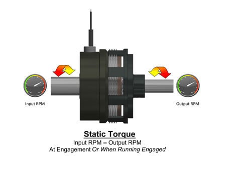
Static clutch and brake usage is simply dependent upon the torsional load. To achieve static torque operations in a clutch, the clutch must be engaged prior to rotating the input such that the clutch acts as a solid coupling between the input and output elements. To achieve static braking, the brake simply holds the output element stationary. In static usage, both the clutch and brake are not absorbing any kinetic energy.

Distinguishing Between Dynamic and Static Torque
Static torque is the "holding" torque that exists when there is no relative speed difference between the input and output shaft in a clutch, and when the shaft is stationary (not rotating) in a brake. The static torque's "breakaway" level must be reached before relative motion will occur between clutch shafts, or before the brake shaft can begin to rotate. Once the relative motion occurs in the brake shaft, or between the input and output in the clutch shafts, the unit's torque capability reduces to a lower value. This value is dependent on the relative speed difference and is called "dynamic torque".
Dynamic torque is typically less than static torque. It will vary with the relative speed difference between the clutch input and output, and the speed difference between the operating speed and the final stop speed (zero RPM) in a brake. This phenomenon is a result of the change in the coefficient of friction within the friction surfaces of the brake or clutch and will vary with the type of friction material used. Since the coefficient of friction will change during the clutch starting and brake stopping, an average coefficient of friction is typically used. The dynamic coefficient of friction is ½ the static coefficient of friction. The dynamic torque is therefore ½ the static torque rating. This is usually associated with an operating speed of 1800 rpm.
Clutch and Brake Torque Transmission Methods
Torque in a clutch or brake can be transferred by two different methods, each with distinct advantages depending on the application. Torque can be transmitted via a jaw tooth friction element or a friction pad (disc).
Jaw Torque Transmission
In general, jaw torque transmission is limited to engagement speed differentials of 100 RPM or less between the input and the output. The number of jaw teeth in the unit also limits the number of available rotary engagement positions. Due to their design, a jaw clutch or jaw brake can transmit more torque in a smaller space compared to friction disc clutch or brake, and tooth forms can be modified to generate specific results.
Friction Pads Torque Transmission
Generally, friction pads or discs have no speed limitations for engagement speeds and can engage in an infinite radial position. The number of discs can also be changed to obtain higher or lower torques with the same actuation.
Torque transmission methods can be combined to offer unique features and multiple functions beyond that of the individual clutch or brake components combined. For example, combining a bi-directional clutch, such as the Carlyle Johnson MTL, and a spring-set friction disc clutch, such as the Carlyle Johnson FEA, the resultant operating features would result in a final component that offers torque limiting, braking, back driving and stopping.

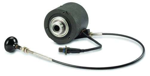
Engaged statically, spring-set brakes can be well-suited to holding applications, as they offer reliable positioning and prevent movement by disengaging when at stop. Most units are remotely controlled but available with a manual release, as shown here on this CJM FEA model, which features a puller cable type mechanism.
Dynamic Brake and Clutch Selection
The selection of a clutch or brake for a dynamic application requires the review of three characteristics:
- What is the capability of the main driver in the system? This involves a review of the prime mover or driver (such as the motor input).
- What is the time required to bring the clutch output speed up to the clutch input speed – or for a brake, what is the time required to bring the shaft speed and torsional load to zero (0) RPM? One must determine if the application has time limitations, and must compare the time requirements to clutch and brake capabilities.
- What is the number of cycles the clutch or brake will be subjected to? It is necessary to evaluate heat dissipation capabilities of the clutch or brake to ensure they are sufficient for the specified use. If the cycle rates are greater than 5, equally spaced over an hour time frame, then this factor should be considered.
Evaluating the Dynamic Clutching or Braking System Mover/Driver
The first characteristic of a dynamic clutching or braking application that should be evaluated is the prime mover or driver of the system (the motor input). The motor will drive the load, and once the motor is specified, the clutch or brake can be sized based upon the motor.

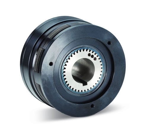
When evaluating which clutch or brake to select, it is important to consider installation and performance criteria as well as unit capabilities. Shown here, both the clutch and brake models of the EMA800 can be adapted for high-speed applications, and feature three balancing holes in the unit’s body for dynamical balancing.
In a dynamic clutching or braking application, the required torque can be calculated using the horsepower rating of the prime mover and the operational speed of the clutch or brake. The calculation is as follows:
Torque (dynamic) is measured in lb-ft.
RPM is the relative speed difference between the clutch input and the clutch output, or the rotational shaft speed of the brake that must be stopped in revolutions per minute (RPM).
HP is the motor’s rating in Horsepower (HP).
SF is the adjustment for the type of driving member (motor) that is utilized.
The SF adjustment is meant to adjust the torque capability of the clutch or brake for the type of driving member (motor) that is utilized. This factor will adjust for the typical torsional load produced in the operational cycle of the motor. For example, the power stroke in a diesel motor will produce large torque spikes throughout the compression and exhaust cycles as each piston moves. These torsional loads will be directly driven through the clutch or brake. On the other hand, the torsional loading from a DC motor will be almost constant. The general SF numbers utilized for each motor type is as follows:
DC Motor = 1
Gas Motor = 1.5–2
Diesel Motor = 2–3
This SF number can be reduced if a flexible, torsional or torsional absorption coupling is used after the motor and prior to the clutch input. The coupling will greatly reduce the torque spikes from the motor. Carlyle Johnson offers some special clutches with integral torque absorption.
Example:
A 10 hp DC motor runs at 1800 RPM and drives a conveyor through a 25 to 1 gearbox. The operator would like to disengage the conveyor from the motor to clear a jam without stopping the motor or the gearbox output, simply by turning a clutch on and off. To determine the clutch torque rating needed, one must calculate:
T=(5250*10)/72 =729.17 lb-ft. (SF=1)
Note: The clutch is located after the gearbox and the shaft speed after the gearbox is 1800/25 or 72 RPM.
Determining Load Drive Time and Stop Time
The time to stop the load (in the case of a brake) or to bring the load up to full speed (in the case of a clutch) is a function of the inertial load that the clutch or brake must start or stop. The time can be calculated as follows:
t (seconds)=(WK^2)(N)/(308*Torque)
t = Time (sec)
(WK^2) = Inertia (lb-ft^2) of the clutch or brake and system (load)
T = Dynamic torque rating of the clutch or brake (lb-ft)
N= (RPM) Operating speed, the speed the clutch must accelerate the load up to, or the speed the brake must stop the load from
Note: The clutch or brake supplier can provide data for the inertia of the rotational components of the brake or clutch. These values must be included in the calculated inertia load of your system.
If the total inertia load is determined to be 50 lb-ft^2, the operating speed is 72 RPM and the dynamic torque rating of the clutch or brake is 730 lb-ft, then the time required to accelerate or stop the inertia load is calculated as follows:
t=( 50)*(72)/(308*730)= .016 seconds
Note: The calculated time to stop the load, or bring the load up to full speed from zero RPM, does not include the time required for the clutch or brake to react to the actuation method. For example, in an electromagnetic clutch or brake the coil must charge and produce an electromagnetic field to activate the armature and create torque through the friction disc(s). This loss of time can range from 10 to 500 milliseconds, depending upon the size of the clutch or brake. The total time - from the time the clutch or brake is switched on, to the time for the clutch to accelerate the load or for the brake to stop the load - must include the inherent engagement time of the actuation method.
The dynamic torque rating of the clutch or brake can be increased by selecting a larger size unit which reduces the total engagement time, if desired. It should be noted that the dynamic torque will also increase, as will the shear forces placed on the mounting components between the rotating and nonrotating members. The torsional force applied to the nonrotating members, such as keys and set screws, should be considered.
Clutch or Brake Cycle Rates
The cycle rate is defined as the number of times the clutch or brake will be turned on per minute. This is the amount of energy the clutch must absorb from a stop or start, and the amount of energy the clutch or brake can dissipate before the next start or stop cycle. Energy is dissipated in the form of heat, and each clutch or brake has a defined heat load capability that can be obtained from the manufacturer.
Data provided typically represents an average cycle rate, and if multiple cycles are performed periodically, then the cycle rates must be adjusted to account for a peak at some point in the total cycle. For example, the heat generated from 10 cycles per hour (that are equally spaced during the hour) will differ greatly from that of 10 cycles per hour if the 10 cycles are performed in the first 5 minutes of operation and no additional cycles occur until the end of the hour.
It should also be noted that heat dissipation will vary significantly depending upon the ambient temperatures and the environmental conditions the clutch and brake are subject to.
The formula to determine the heat loading is:
E=BTU/Min= 1.7 (Wk^2)(RPM/100)^2(Engagements per minute)/780
Wk^2: Inertia (lb-ft^2) of the system including the clutch non-rotating component
RPM: Operating speed, the speed the clutch must accelerate the load up to, or the speed the brake must stop the load from.
Example:
A clutch input is running at 1800 RPM and the inertia load to be accelerated from zero to 1800 RPM is 2.5 lb-ft^2. The application will require the clutch to engage and disengage 10 times per minute. The calculation for the heat load that must be dissipated is as follows:
E=(1.7*2.5*(1800/100)^2*10)/780= 17.65 BTU/Min.
The clutch selected must be capable of dissipating at a minimum of 17.65 BTU/Min.
Clutch and Brake Actuation
Clutches and brakes can be actuated with several different methods, and all have unique positive and negative aspects. The typical actuation methods are mechanical, electromagnetic, and hydraulic/pneumatic.
Mechanical Actuation
Mechanical actuation is typically performed with a handle that utilizes a mechanical advantage through a lever system for easy engagement and disengagement. The mechanical advantage is used to squeeze friction discs (one or several) together to transmit torque. When the handle is moved to another position, the clutch or brake condition (engaged or disengaged) changes. Mechanical systems can be offered with an internal locking mechanism so that, once the clutch is engaged or disengaged, it will remain in that condition without the need for a constant external force.
Mechanical Actuation Advantages
Mechanical clutches and brakes feature a robust design, with no bearings to fail. The units are not affected by power failures that can be the result of changes in power supplies, changes in pneumatic or hydraulic pressures, or from power outages. Mechanical clutches and brakes are also somewhat speed tolerant. Units are easily available with single position configurations, or with automatic overload release in case of a jam or over-torque condition.
Mechanical Actuation Disadvantages
Mechanical clutches and brakes will not automatically disengage with loss of power. These units also periodically require manual adjustment to account for wear on the friction discs over use age.
Electromagnetic Actuation
Electromagnetic actuation is performed by a magnetic coil and an associated magnetic flux path incorporated within the clutch or brake. The magnetic field created is typically used to move an armature and squeeze friction surfaces of the discs (one or several) together or to move the armature from contact with the friction discs when in a spring-applied design.
Electromagnetic Actuation Advantages

AHA25 pneumatic (hydraulic) clutches and brakes, as shown above, are rated from 15 lb.ft. dynamic to 60 lb.ft. of static torque, and torque can be regulated by adjusting systems pressures. These units are designed with a stationary cylinder assembly that is mounted on deep-groove ball bearings to accommodate thrust loads.
Electromagnetic clutches and brakes can be supplied with either an energy-applied system or with a spring-applied/energy-deactivated system, which provides flexibility to the design. This will also cause the clutch or brake to turn on or turn off when power is lost. Electromagnetic clutches and brakes provide a long service life if utilized correctly. These units are somewhat speed tolerant, and can also be modified to increase tolerance of speeds. These clutches and brakes are available with self-adjustment features to compensate for wear on the friction discs.
Electromagnetic Actuation Disadvantages
An electromagnetic clutch requires bearings to support the stationary coil field. These bearings will be subject to loading due to the use of a radial flux path and, although loads are usually extremely light, this can be a concern for the engineer. Additionally, the time required to engage an electromagnetic clutch or brake can be greater than the engagement time of other actuation types due to the time required to build up the coil’s magnetic field.
Hydraulic/Pneumatic Actuation
The hydraulic/pneumatic actuation of a clutch or brake is accomplished by pushing a piston to squeeze one or several friction discs together to transmit torque. This transfers torque from the input shaft to the output shaft.
Hydraulic/Pneumatic Actuation Advantages
Hydraulic/pneumatic clutches and brakes offer fast response times based upon the actuation pressure and the clutch piston mass. Their design produces consistent engagement times based upon the control pressure variations.
Hydraulic/Pneumatic Actuation Disadvantages
In a hydraulic or pneumatic application, the full force produced by the piston must be transmitted through a bearing – this allows the clutch body to rotate while the housing remains stationary. These bearings must be properly selected to ensure a reasonable service life. Additionally, due to the use of bearings and the high loads experienced by the clutch, operating speeds are limited. The hydraulic/pneumatic brake does not require a bearing.
Wet Running Clutch and Brake Applications
Wet running clutches and brakes require the same analysis as dry running applications (outlined above). However, because the unit will be exposed to fluid or lubricant, the coefficient of friction will change significantly.
Wet running applications also require an enclosure for the clutch or brake, which affects heat generation and dissipation, and therefore must be analyzed further.
Oil shear is a major factor in wet running applications, as the clutch or brake will generate a significant amount of heat – even in the neutral mode – because of oil shearing between the friction disc(s). Oil shear between the friction disc(s) will occur until the output and input speed in a clutch or brake are almost equal, which will also affect clutch and brake engagement times.
While a wet running application significantly reduces wear on friction discs, due to heat concerns, the application should be completely reviewed to ensure the proper selection of a clutch or brake.
Summary
Proper clutch and brake selection is vital to ensuring long-life, optimal performance and reliable operation. Numerous factors must be taken into consideration during the selection process, including time requirements, cycle rates and the evaluation of the system mover/driver. It is also important to understand the differences between dynamic and static applications, actuation methods and wet and dry running applications. These factors should all be taken into consideration during the dynamic brake and clutch selection process to utilize the appropriate option for different applications.
Contact Our Dynamic Brake and Clutch Experts
If you have questions about dynamic brake or clutch selection or about the information detailed throughout this article, our team is here to help. Fill out the form on this page or reach out and we will contact you shortly.
Overview
Advantages of Electric
Clutch & Brake Engagement
- Longer life and higher speeds due to reduced bearing loading
- No additional solenoids or switches are needed to energize the coil
- Devices are self-adjusting for wear compensation
Advantages of Spring Applied - Electrically Released Clutches & Brakes
- Automatic engagement upon power loss
- No additional solenoids or switches are needed to energize coil
CJM ELECTRIC CLUTCH & BRAKE PRODUCTS
- JEB Model Electric Jaw / Tooth Clutches
- JEB Model Electric Jaw / Tooth Brakes
- FEA Model Fail-Safe, Spring Set Electric Clutches
- FEA Model Fail-Safe, Spring Set Electric Brakes
- EMA Model Multiple Disc Electric Clutches
- EMA Model Multiple Disc Electric Brakes
- EPC Model Sheave / Pulley Clutches
- JEM Model Zero Backlash Electrical Clutches
- JEM Model Zero Backlash Electrical Brakes
- HTB Model High Torque, Spring Applied Brakes
- EFS Model Spring Set Electric Brakes
CJM ELECTRIC CLUTCH & BRAKE PRODUCTS
Downloads

Upload a CAD for a custom torque limiter design.


